Kristen Heaton
Summer 2017
Over the summer of 2017, I was selected by my design two professor to design and build the final human powered vehicle for the client and end user. The goal was to design and build from scratch a frame that could have a trike adapter but eventually be converted to a two wheel bike with the balance improvements of the end user. This project had me working with my engineering lab manager to fabricate the vehicle's frame using a mill, a lathe, a drill press, and other power and hand tools.
Frame Inspiration
After the tests with the client and end user at the end of May, this design's frame from another team had the perfect dimensions for our rider, leading it to be the basis for a new design.
Horizontal Dropouts

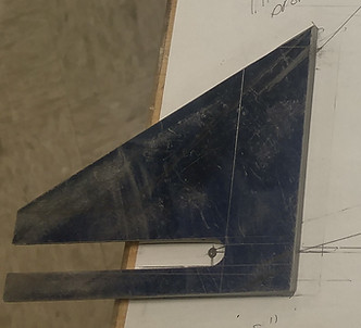

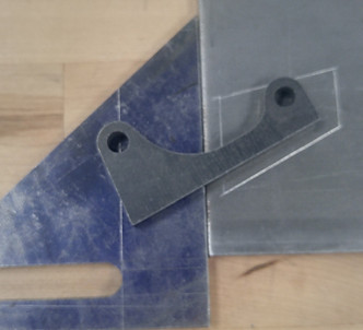
(Clockwise from upper-left). One of the features needed to ensure a better fit of a trike adapter from another design were horizontal dropouts. To determine the best slope for the triangular portion of the dropout, I utilized cardboard aided drawing to compare different slopes to the base frame to find the best angle (~33 degrees). I then modeled the dropout using SolidWorks so that I could have a better idea of the dropout in 3D and more official measurements. This lead me to the engineering machine shop to fabricate the dropouts using .25 inch steel and a mill machine. The last requirement was to make the left rear dropout disc brake ready by welding an additional piece of metal onto the dropout. This will allow for a brake caliper to be added on when the vehicle goes from three to two wheels.
Trike Adapter
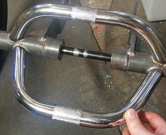


Another part of this project was to modify a trike adapter that a previous team had made for their human powered vehicle. To make it ready for my overall plan, brackets for a disc brake caliper needed to be welded via my lab manager onto the axle bars. Also, to allow for a basket to be placed onto the adapter, bars were welded onto the dropouts. The last step for this was to prime the trike adapter for later painting.
Frame


After measuring the frame from above, I modeled the new frame in SolidWorks 2016. This would help me to get a sense of it's final form before fabrication. I then drew a full scale paper version of the frame. This would allow for pre-welding checks to make sure that all the pieces lined up together. The image on the middle right is a progress photo after the top and bottom tubes, the head tube, and the seat tube were welded onto the bottom bracket shell. The top and bottom tubes were curved so that my end user would have a lower step through to allow for easier mounting and dismounting. The last image is the final frame, welded and ready for assembly.
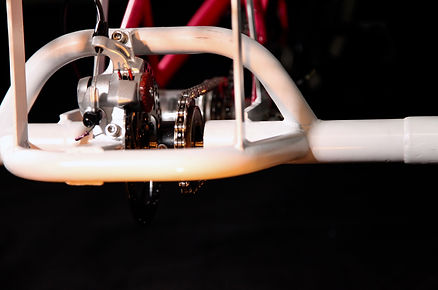
Testing


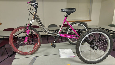
After mounting the trike adapter and collecting remaining parts, the vehicle went into testing by my professor, myself, and my end user. At this stage, the vehicle's subsystems of steering, propulsion via a 3-geared Sturmey-Archer hub, and braking via front and rear disc brakes, were all functional. Minor adjustments to each subsystem were needed before the vehicle was ready for hand-off in October 2017.
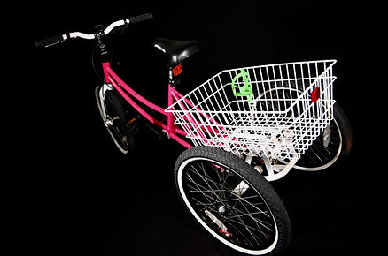
Final Human Powered Vehicle
The final part of this experience was having a hand off ceremony between the James Madison University Department of Engineering, the client, and end user. These are some of the photographs of the final painted and assembled human powered vehicle.


My Channel
To continue to my two-year capstone work, click this button here.